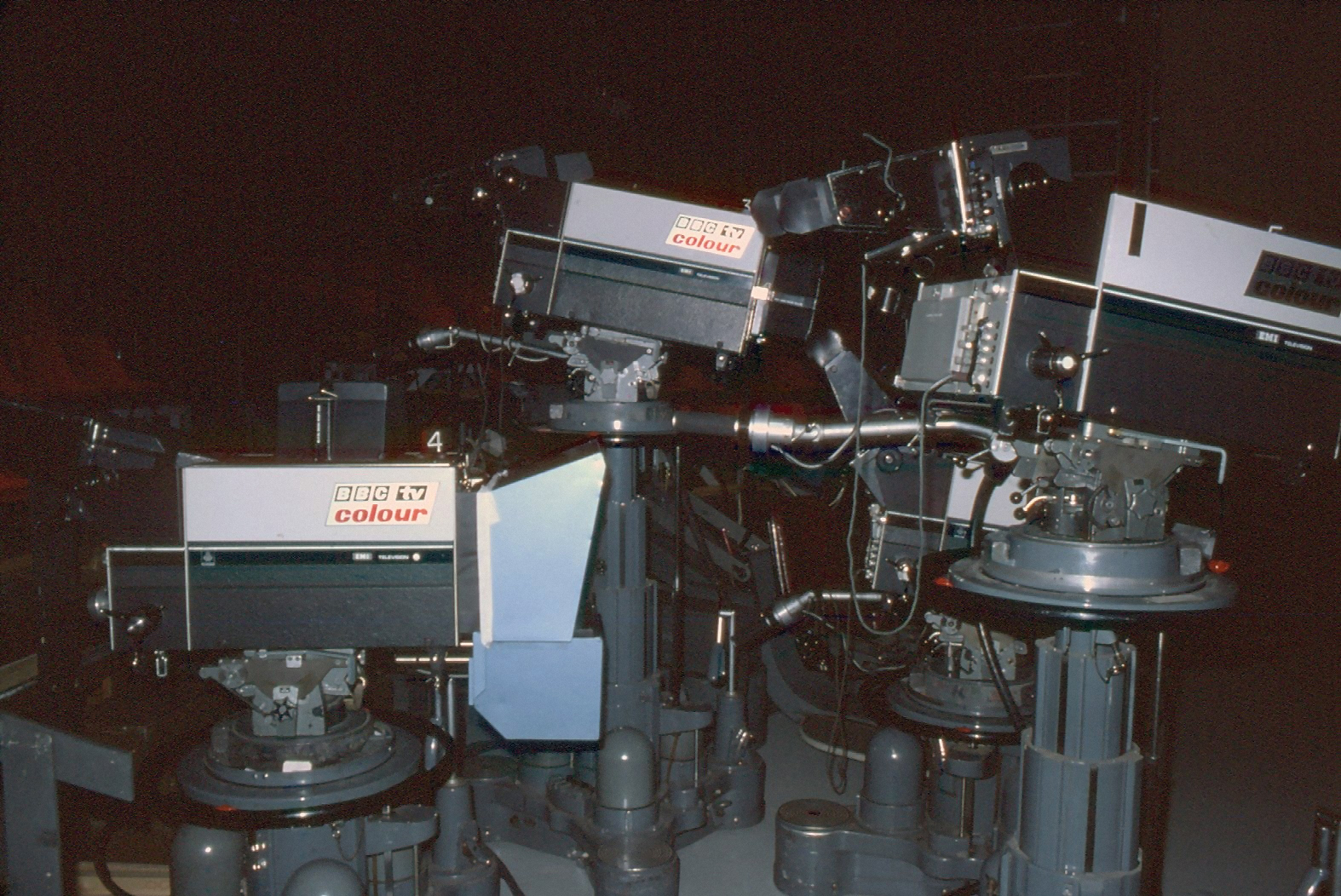
Studio A EMI 2001 line up. Photo by John Kimberley, no reproduction without permission.
The Cameras
Both Studio A and B were equipped with EMI 2001 cameras, which were unique in using four 1.25 inch camera tubes. Unlike most of the other colour cameras which used just 3 tubes, the EMI’s had a 4 way light splitter block (the ice block) which allowed a full spectrum image to the Luminance tube, and then split to red, green and blue for the colour images. The reason for this was that it meant only the luminance channel needed to be a full bandwidth channel, as this was the one channel to define the image sharpness and detail. The colour channels could get away with a lower bandwidth, and thereby were less critical. The downside was lack of sensitivity, as the luminance split effectively halved the sensitivity for the same amount of light. This meant Studios had to be lit very brightly, with a lot of lighting power.
Other manufacturers used only a 3 way colour split and had the green channel as the full bandwidth channel, to provide the detail information. This maintained sensitivity, but because the image was the filtered green image, this did not always work as well as a full spectrum image.
One of the problems of the early colour cameras was the lack of sensitivity to the red end of the spectrum, and this was particularly so with the EMI’s. It most noticeably showed up with purples and magentas which were invariably seen as blue by the cameras. Later cameras used extended red response tubes, and generally seemed to produce rather more saturated colours than the EMI’s could, but few seemed able to match the image sharpness and crispness which seemed so characteristic of the EMI’s
Prior to every studio booking the cameras needed alignment. This was because the electronics of that era tended to drift with temperature, and the camera tubes themselves drifted being thermionic devices. Also the length of cable between the camera and CCU had a big effect on the camera signal, and had to be compensated for by the electronics. The cameras were all set up looking at a grey scale chart, and adjustments were made on the CCU to ensure that all the colour channels were giving the same signal level, in order that the combined output was neutral grey, at the different brightness levels of the chart. The light on the chart was adjusted to give a colour temperature of 2950 and a light level of 1600lux using a special light meter called a Collux.
The cameras were also aligned on a registration chart. This was a grid of lines which enabled adjustments to be made so that the images from each tube exactly over-laid each other. If these adjustments were wrong coloured fringes would appear at the edges of objects.
One of the first jobs I did after starting to work in studio ops. was to write up a set of alignment instructions for the cameras. It helped me to effectively learn more about the cameras and how they worked, and also gave a set of standardised methodical adjustments to aim to get the best out of the cameras, that all the engineers could use. I am grateful to Peter Hodges for pushing me to do this in the early days, as it really helped ground me in the basics. Whether other engineers actually found it helpful I don’t know, or whether they even referred to them, but at least they were available where before there was nothing written down.
Ray Lee